Running Asynchronous Jobs With Push Buttons
This experiment is very useful and needed in many projects later on, and I focus on things in a practical manner. So let’s get going.
Things we’ll need
- A raspberry pi board with its adapter, any version will do. I’ll be using pi 3 model b
- Tactile push buttons, the simplest ones
- 2 resistors, 1k ohms and 10k ohms
- A capacitor, 0.1 micro farad or 100nF
- One Schmitt trigger IC, SN74HC14N will do
- A bread board, and jumper wires (female to male)
the button driver circuit diagram
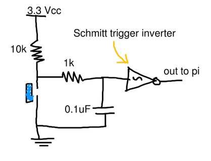
The output of this circuit will be connected to an input in the raspberry pi, and since the button will be driving Raspberry pi inputs which take 0 for low and 3.3 for high readings, so the source and ground will be provided by the Pi itself.
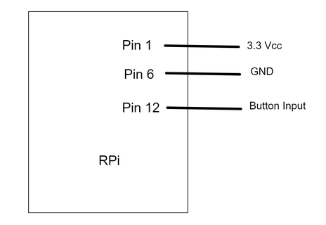
In the above diagram, Button input is connected to pin 12 which is BCM/GPIO 18 in this case, take note of this in the software next.
The raspberry pi 3.3v and 5v pins are supplied directly from the adapter (the original adapter of the Pi can provide up to 2.5 Amps), which is enough to drive out components, but current draw should always be calculated and considered in all circuit designs.
The software
There are different ways (programming languages) that have libraries to deal with the Raspberry pi. I’ll be using Python, which seems a very common choice for its power and ease of use (the code is very readable).
#!/usr/bin/python import RPi.GPIO as GPIO import time GPIO.setwarnings(False) GPIO.setmode(GPIO.BCM) BTN_PIN = 18 # setting inputs GPIO.setup(BTN_PIN, GPIO.IN) # this runs when a change of state happens on pin 18 # non blocking def btn_callback(channel): if GPIO.input(BTN_PIN): # execute python code... # you can do many exciting things here, like: # control outputs of the pi,driving other circuits # turning something on/off, play some music... print("Button was pressed.") raw_input("Press Enter when ready\n>") # this sets interrupt detection on both falling and rising edges of pin 18 (the button) # software bounce of 100 millisecond GPIO.add_event_detect(BTN_PIN, GPIO.BOTH, callback=btn_callback, bouncetime=100) try: # this is actually the running program, just blocking. while True: time.sleep(1) except KeyboardInterrupt: GPIO.cleanup() GPIO.cleanup()
some explanations
why use the hardware debounced circuit?
it is used to smooth out transitions between low and high voltages, and cancel out noise. Basically to read the signal we’re really expecting.
why use a Schmitt trigger IC?
This will further refine the output signal, it uses what is called hysteresis or two threshold voltage levels on low and high voltages. It’s very useful to cancel out errors on a noisy input like the button here.
What is software denouncing?
This is actually done automatically with the GPIO module (and very recently included), it takes many reads for the input separated with the bounce time we set, it only detects a raising edge if for example the pi reads (0v, 3.3v, 3.3v) successively and waiting 100 ms each time.
This technique will cancel out noise, and a 3.0 volts signal for 30 ms will not be detected as a raising edge.
How to decide on software bounce time?
This is actually done with some experimentation, and depends of the physical properties of the button itself. A good value will be between 50 to 100 ms for this circuit.
Now we can take user input from push buttons (obviously seen in many devices). Next and in future circuit designs, we’ll use this button diagram to get user input and do some awesome stuff.